Mechanical gears, which serve as essential components in a wide range of machinery and vehicles utilized in our daily lives, are intricate mechanisms designed to facilitate the transmission of motion and force between different sections of a given machine. There is a wide range of shapes, sizes, and designs available for these objects, and each variant exhibits distinct attributes that render them appropriate for particular uses. This article aims to explore the intricate realm of mechanical gears, offering insights into their functionalities, various classifications, underlying mechanisms, and real-world utilizations.
The Core Functions of Mechanical Gears
Gears, those mesmerizing mechanical wonders, are like the unsung heroes of the industrial world. These small yet mighty components play a pivotal role in an array of machinery, from clocks and watches to complex automotive systems and heavy machinery. Their ability to efficiently transfer power and motion has revolutionized the way machines function. Mechanical gears essentially perform three vital tasks:
Changing the Direction of Rotation
Imagine two gears harmoniously interlocked, with their teeth delicately meshing like a well-choreographed dance. When one gear decides to turn right, its partner will gracefully mirror the motion but, instead, turn left. This enchanting play of direction change is one of the most fundamental tasks of mechanical gears. The elegant interplay between the gears allows machinery to change the direction of power transmission, enabling the seamless functioning of many mechanical marvels we encounter daily.
Take a closer look at this captivating phenomenon in the table below:
| Input Gear Rotation | Output Gear Rotation |
|---|---|
| Clockwise | Counterclockwise |
| Counterclockwise | Clockwise |
Adjusting Speed of Rotation
The marvel of how gears can either hurry or slow down the rhythm of rotation! This magical transformation of speed is intrinsically linked to the size relationship between the interlocking gears. As if performing a well-practiced symphony, a larger gear turning a smaller gear sets the stage for a faster-paced performance by the smaller gear. Conversely, a smaller gear in charge of driving a larger gear leads to a slower and more deliberate rotation.
Discover the captivating dance of speed adjustment in the table below:
| Input Gear Size | Output Gear Size | Output Speed (Relative to Input) |
|---|---|---|
| Larger | Smaller | Faster |
| Smaller | Larger | Slower |
Altering the Force
Gears, like magicians, have the power to manipulate forces, making heavy burdens feel lighter or lighter tasks feel weightier. The secret lies in the size relationship, just as with speed adjustment. When a larger gear propels a smaller gear, the force diminishes, as if it were a whisper. On the contrary, when a smaller gear takes charge of turning a larger gear, the force amplifies, akin to a roaring thunder.
Witness the captivating spectacle of force alteration in the table below:
| Input Gear Size | Output Gear Size | Output Force (Relative to Input) |
|---|---|---|
| Larger | Smaller | Reduced |
| Smaller | Larger | Amplified |
Gears, in their eloquent simplicity, have transformed the world of mechanics, unlocking possibilities and ushering progress. Their ability to change the direction of rotation, adjust the speed of rotation, and alter the force applied has undoubtedly earned them a well-deserved place at the heart of modern engineering. Next time you marvel at the ticking of a clock or the smooth maneuvering of a car, take a moment to appreciate the captivating and unique role played by these magical mechanical gears.
Key Components of a Gear System
A gear system comprises several components that all work together to perform the tasks mentioned above:
- Gear Teeth: These are the projections on a gear that interlock with the teeth of another gear to transmit torque;
- Pitch Circle: This is an imaginary circle that runs through the point where gear teeth ideally meet.
- Pitch Diameter: The diameter of the pitch circle is known as the pitch diameter;
- Addendum: This is the radial distance from the pitch circle to the top of the gear tooth;
- Dedendum: The radial distance from the pitch circle to the bottom of the gear tooth is known as the dedendum;
- Pressure Angle: This is the angle at a pitch point between the line of pressure (which is normal to the tooth surface) and the plane tangent to the pitch circle.
Summary of Gear Components
| Component | Description |
|---|---|
| Gear Teeth | Projections on a gear that interlock with another gear’s teeth. |
| Pitch Circle | An imaginary circle that runs through the point where gear teeth ideally meet. |
| Pitch Diameter | The diameter of the pitch circle. |
| Addendum | The radial distance from the pitch circle to the top of the gear tooth. |
| Dedendum | The radial distance from the pitch circle to the bottom of the gear tooth. |
| Pressure Angle | The angle at a pitch point between the line of pressure and the plane tangent to the pitch circle. |
Types of Mechanical Gears
Mechanical gears come in a variety of shapes and sizes, each designed for specific tasks. The primary types include:
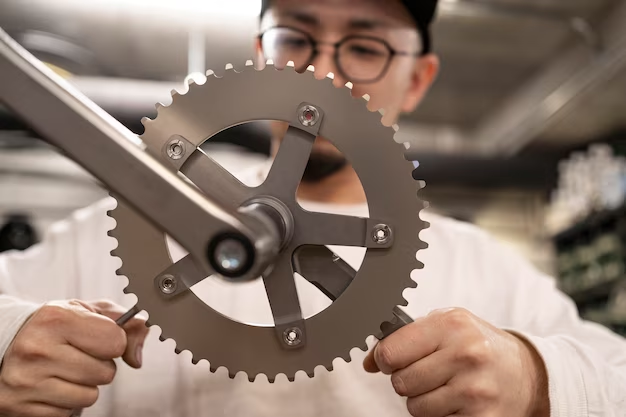
- Spur Gears: The simplest and most common type of gear, with teeth that are parallel to the gear’s axis. They are used in many applications, including clocks and car engines;
- Helical Gears: These gears have teeth cut at an angle to the gear’s axis, allowing for smoother and quieter operation compared to spur gears. They are commonly used in high-speed applications;
- Bevel Gears: Bevel gears’ teeth are cut on a cone, allowing them to transmit force between two intersecting axes. They are commonly used in differential drives, which allow the outer drive wheel to rotate faster than the inner drive wheel;
- Worm Gears: A special type of gear, consisting of a ‘worm’ and a ‘worm wheel’. The worm, which resembles a screw, meshes with the worm wheel to transmit motion at a 90-degree angle.
For a better understanding of these gears and their functioning, consider checking out this video:
Applications of Mechanical Gears
Mechanical gears find utility in a wide array of applications. From small machines to large industrial equipment, the versatility of gears is truly remarkable.
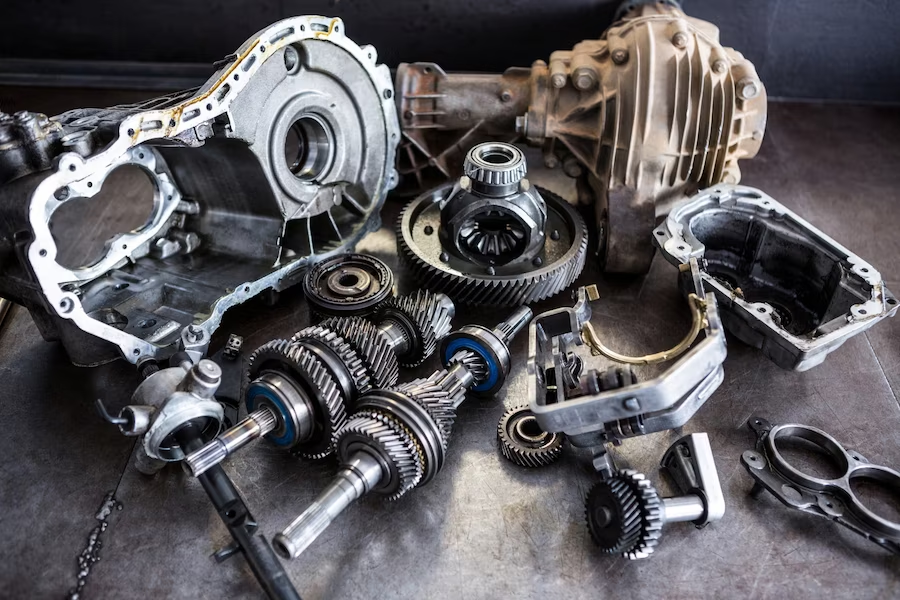
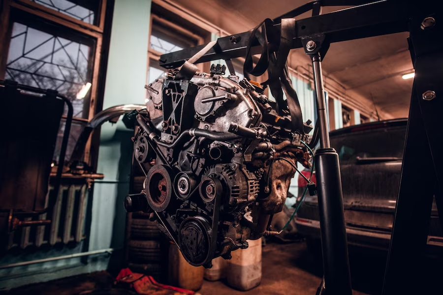
- Automobiles: Gears are at the heart of a vehicle’s transmission system, allowing the engine’s power to be varied to drive the vehicle at different speeds;
- Clocks and Watches: In horology, different types of gears, especially spur gears, are used to drive the hands of clocks and watches;
- Industrial Machinery: Gears are critical components in many industrial machines, from conveyors and cranes to mills and production line equipment;
- Household Appliances: Items like washing machines, electric drills, and kitchen mixers all use gears to convert electrical energy into mechanical energy.
Conclusion
Mechanical gears, despite their seemingly simple appearance, are complex mechanisms with a plethora of uses in various fields. Their importance in everyday life cannot be understated, and understanding their functioning offers a deeper appreciation of the machinery that powers our world.
FAQ
Gears can be made from a variety of materials depending on the requirement, including metal (such as steel or brass), plastic, and even wood in some cases.
Yes, gears of different sizes are often used together to change the speed of rotation or the amount of force applied.
The gear ratio is the ratio of the number of teeth on two gears that are meshed together. It is used to calculate the speed and force changes in a gear system.