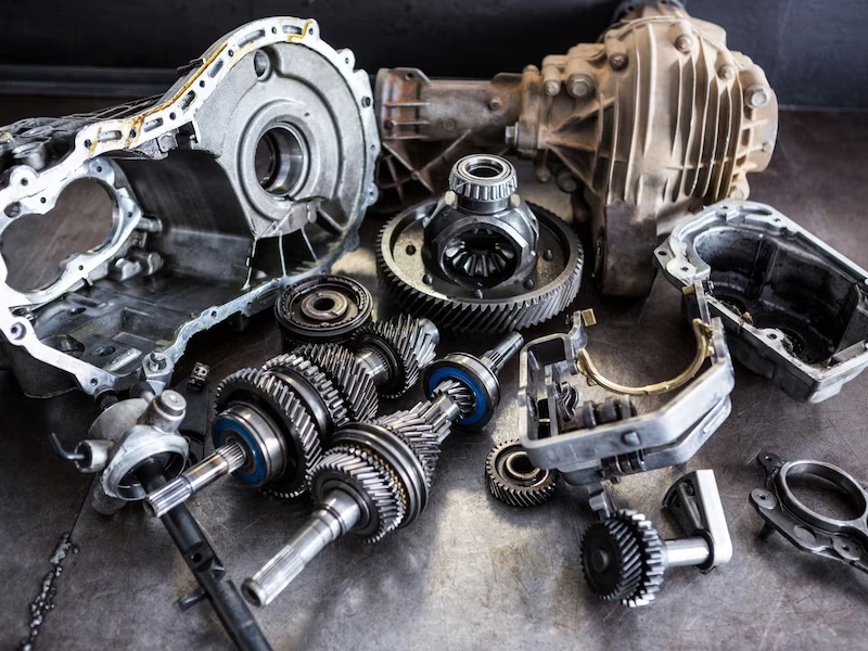
In the ever-evolving world of modern CNC machining, cutting-edge systems possess a remarkable ability to directly interpret parts’ geometry from 3D CAD design files, streamlining the manufacturing process. While technical drawings may not be mandatory for requesting quotations, they remain an integral and widely practiced aspect within the industry. These technical documents play a crucial role in enhancing communication between designers, engineers, and machinists, acting as a common language that facilitates a seamless exchange of technical requirements. To ensure streamlined and efficient cooperation throughout the CNC machining process, it is strongly recommended to prepare a comprehensive technical drawing alongside your CNC order. By providing detailed insights into your project’s specifications and intricate details, the technical drawing empowers our team to understand your design intent thoroughly. This collaborative approach guarantees a smoother workflow, enabling us to meet your precise requirements with utmost accuracy and deliver impeccable results.
Embracing technical drawings in your CNC order not only showcases your commitment to precision but also ensures clarity in design intent. By equipping our team with the essential information needed to execute your project, we can optimize our efforts to achieve outstanding outcomes that exceed your expectations.
Incorporating technical drawings as an integral part of your CNC machining process showcases a dedication to quality and precision, fostering a successful partnership between you and our team. Together, we can create exceptional results that bring your designs to life with precision, efficiency, and excellence.
The Significance of Technical Drawings in CNC Machining
In the realm of CNC machining, technical drawings play a crucial role as indispensable documents, complementing 3D CAD files and contributing significantly to the manufacturing process. These essential documents serve various pivotal functions, highlighting their indispensability:
- Describing Complex Features: Technical drawings provide a means to describe intricate features that may not be fully encompassed in a 3D CAD model. Examples include external and internal threads, which are critical for precise machining;
- Communicating Specifications: Dimensions, annotations, and tolerances specified in the technical drawings offer manufacturers a comprehensive understanding of the precise requirements for fabricating the part. These details are instrumental in achieving accurate and high-quality results;
- Conveying Special Requirements: Technical drawings allow part designers and engineers to provide explicit instructions for special requirements, such as surface roughness and finishing, ensuring that the final product meets desired specifications.
Regardless of whether your part design seems simple without intricate features or special requirements, it is still highly advisable to include technical drawings alongside your 3D model. Manufacturers depend on these drawings as vital references throughout the entire manufacturing process, guaranteeing uniformity and accuracy in the CNC machining operation.
The Importance of Technical Drawing
In every CNC order, your technical drawing serves as a vital companion to the 3D CAD file, encompassing crucial elements that are challenging to convey in the digital realm alone. Elements like threads (internal or external), features with exceeding standard tolerance, and surfaces with specific finishes find their explicit representation in the technical drawing. Even if your CNC design does not involve these elements, incorporating a technical drawing alongside the 3D CAD file is an excellent practice.
While the 3D CAD file is utilized for CNC machine programming, the technical drawing plays a pivotal role as a machining process reference. Many CNC service providers prefer technical drawings over 3D CAD files due to several compelling reasons:
- Expert Interpretation: Machinists are proficient in interpreting parts’ geometry from 2D drawings, ensuring precise execution of design intent;
- Clarity and Identification: 2D drawings make it easier to identify main dimensions, functions, and critical features of the parts, promoting a clear understanding of the project requirements;
- Cost Assessment: With technical drawings, assessing parts manufacturing costs become more accessible, enabling efficient project planning.
Technical drawing holds immense importance in the realm of CNC machining, serving as a fundamental communication tool between designers, engineers, and machinists. As CNC machines continue to interpret 3D CAD design files with remarkable accuracy, one might question the necessity of technical drawings. However, these drawings play a pivotal role in conveying precise design specifications and intricate details that are crucial for a successful CNC machining process. By providing a comprehensive technical drawing alongside CNC orders, designers empower machinists with essential insights, ensuring seamless collaboration and a clear understanding of the project’s requirements. The use of technical drawings guarantees precision, clarity, and effective communication, leading to superior results that surpass expectations in the world of CNC machining.
Components of a Technical Drawing for CNC Machining
A well-crafted technical drawing is an indispensable tool in the realm of CNC machining, serving as a comprehensive blueprint that facilitates effective communication between designers, engineers, and manufacturers. Let’s delve into the essential components that constitute a typical technical drawing:
Title Block:
At the outset of the drawing, the title block provides vital information about the part, including its name, material composition, finishing requirements, color specifications, designer’s name, and company details. This crucial data informs manufacturers about the part’s intended function and aids in proper execution. Additionally, technical information such as drawing scale, dimensions, and tolerance standards are specified in the title block. The angle projection, which determines the view orientation and arrangement in the drawing, is also included. Commonly, technical drawings adhere to the ASME standard of 3rd angle projection or the ISO/DIN standard of 1st angle projection.
Isometric or Pictorial View:
To enhance the comprehensibility of the drawing, it is recommended to incorporate one or more 3D pictorial views. These isometric views combine the illusion of depth with undistorted presentation, presenting vertical lines unchanged, while horizontal lines are shown at a 30° angle.
Main Orthographic View:
The main orthographic views are fundamental in transferring the geometry information of the 3D object into a 2D format. These 2-dimensional depictions represent the precise shape of the part from one side at a time. All part edges are drawn in these views to clarify the communication of dimensions and features. In most cases, two or three orthographic views sufficiently describe the entire geometry of the part with accuracy.
Section View:
Section views are employed to present the internal details of the part. Cutting lines in the main orthographic views indicate the parts’ cross-sectional area, and a cross-hatch pattern in the section view depicts material removal regions. Multiple section views are designated with two letters linking each cutting line, such as A-A, B-B. Arrows on the cutting lines indicate the viewer’s direction. While hidden internal features can be represented with dashed lines in the orthographic view, section views offer greater clarity.
Detail View:
To emphasize complex or intricate dimension areas in the main orthographic views, detail views are added. Placed offset from the main drawing to avoid confusion, detail views are annotated with single-letter links like A, B, etc. These views can be positioned anywhere on the drawing with varying scales to enhance communication.
Notes for Manufacturer:
In the notes section, manufacturers receive additional instructions that may not be explicitly included in the technical drawing. These notes may convey directions regarding sharp edge breaks, deburring, and specific surface finish requirements. In some cases, symbols are employed instead of text for brevity and clarity.
Preparing a Technical Drawing for CNC Machining: A Step-by-Step Guide
When it comes to preparing a technical drawing for CNC machining, a systematic approach ensures the best results. While the process may vary depending on the complexity of the part, the following steps outline the fundamental process for creating a comprehensive technical drawing:
- Step 1: Identify Important Views and Placement
Determine the crucial views required for your part and position the orthographic views at the center of the drawing. Allow sufficient space between views to accommodate dimensions;
- Step 2: Addressing Intricate Features
For parts with intricate features or challenging-to-dimension areas, incorporate detail views or section views to provide a clearer representation;
- Step 3: Integrate Construction Lines
Add construction lines to all views, including centerlines, center marks, and center mark patterns. These aid in defining planes, axes of symmetry, and the location of hole centers or circular patterns;
- Step 4: Dimensioning the Drawing
With construction lines in place, proceed to add dimensions to the drawing. Start by detailing the most critical dimensions for accurate manufacturing;
- Step 5: Specify Threads
Clearly indicate the location, length, and size of all threads within the technical drawing;
- Step 6: Addressing Tolerances
For features requiring higher accuracy than standard tolerances, include additional tolerance information to ensure precise machining;
- Step 7: Completing the Title Block and Notes
Fill out the title block with all relevant information, including part name, material, finishing requirements, and designer details. Include specific instructions, such as surface finish and deburring requirements, in the notes section for the manufacturer.
Mastering the Art of Technical Drawing in 7 Steps
Creating a comprehensive technical drawing requires careful planning and attention to detail. Here is a concise overview of the essential steps to follow in your technical drawing process:
| Steps | Description |
|---|---|
| Define Important Views | Identify the key views required for your part and place the relevant orthographic views at the center of your drawing, leaving ample space for adding dimensions. |
| Incorporate Section and Detail Views | For internal features or complex areas that are difficult to dimension, include section views or detail views to provide a clearer representation. |
| Integrate Construction Lines | Add construction lines, such as center lines, center marks, and center mark patterns, to all views, aiding in alignment and precision. |
| Dimension Your Drawing | Begin by adding dimensions to the most critical features, ensuring that they are clearly specified. |
| Specify Threads | Clearly indicate the location, size, and length of all threads in your technical drawing. |
| Include Tolerances | For features requiring higher accuracy than standard, incorporate tolerance specifications to ensure precise manufacturing. |
| Complete the Title Block | Fill in the title block with all relevant information, exceeding standard requirements in the notes section to provide comprehensive details. |
Upon completing your technical drawing, export it as a PDF file and attach it to your order for manufacturing.
While this serves as a basic structure for a technical drawing, keep in mind that specific dimensions, annotations, and tolerances are essential for ensuring the successful execution of your project. Paying attention to these crucial details guarantees that your technical drawing serves as an effective communication tool between designers and machinists, resulting in accurate and high-quality CNC machining.
Dimensions, Tolerance & Annotations in Technical Drawings
In the world of CNC machining, accurate dimensions, tolerances, and annotations are essential for a successful manufacturing process. When your parts design is accompanied by a 3D CAD file, critical dimensions become crucial for the manufacturer to ensure precision and avoid errors during production.
To effectively display critical dimensions in your technical drawing, consider the following tips:
- Place overall dimensions of the parts to provide an encompassing view;
- Add critical dimensions for functional purposes, emphasizing key features;
- Dimension other features from the same baseline for clarity and consistency;
- Place dimensions on views with the most clear description of the feature;
- For repeated features, add only one of them and indicate the total number of repeat features in the current view.
When it comes to hole callouts, consider using symbols such as the depth symbol (↧) to represent secondary features like couterbores and countersinks instead of individual dimensions, enhancing drawing clarity.
When your parts contain threads, it is vital to clearly specify them on the technical drawing. Utilize callouts to define threads, including thread size (e.g., M4) and thread length, to ensure accurate machining.
Tolerances play a critical role in defining acceptable value ranges for certain dimensions, especially for features that interact with other components. Tolerances can be applied to both linear and angular dimensions on the drawing. Bilateral tolerances, symmetrical around the base dimension (e.g., ±0.1 mm), are the simplest form, while unilateral and interference tolerances provide specific requirements for non-symmetrical features.
It is important to note that tolerances are only required when exceeding standard values. In CNC machining, our standard tolerance is typically ±0.125 mm or ±0.005″.By paying meticulous attention to dimensions, tolerances, and annotations in your technical drawings, you ensure a smooth and accurate CNC machining process, resulting in high-quality parts that meet your precise requirements.
Conclusion
CNC machining drawings are essential blueprints that serve as a critical link between designers and manufacturers. These technical documents play a vital role in conveying precise dimensions, tolerances, and specifications, ensuring accurate and high-quality production. By following best practices in preparing technical drawings, such as identifying important views, incorporating construction lines, and detailing critical dimensions, designers can optimize the CNC machining process and achieve successful outcomes. Embracing the significance of these drawings as a fundamental aspect of CNC machining workflow empowers businesses to streamline communication, minimize errors, and achieve superior results in their manufacturing endeavors.