In the world of machining, lathes play a pivotal role in shaping and transforming raw materials into intricate components. To unlock the true potential of lathes, one must grasp the fundamental principles of lathe axes. In this article, we delve into the core concepts, demystify their significance, and equip you with the knowledge to optimize your machining processes. Whether you’re a novice or an experienced machinist, join us on this journey to enhance your understanding of lathe axes and elevate your precision engineering skills.
Evolution of Axis Systems in Lathes: From 2-Axis to 6-Axis CNC Precision
Within the realm of lathe machinery, the axis configuration is the central fulcrum influencing their efficacy, serving as the determinant of the accuracy, intricacy, and adaptability of the machining tasks they can execute. With the passage of time, significant evolution has been witnessed in lathe technology, transitioning from the simple two-axis configuration to the state-of-the-art six-axis Computer Numerical Control (CNC) lathes. These advancements have catalyzed a paradigm shift in the manufacturing sector.
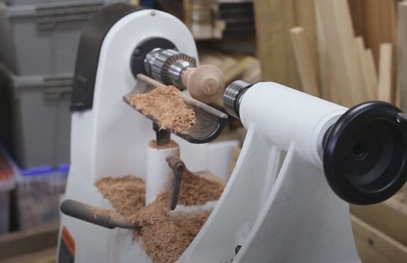
1. The 2-Axis Lathe: Simplicity Meets Versatility
In the early days of manual lathes, simplicity was the name of the game. The classic 2-axis system involved two primary movements: the X-axis, which facilitated front-to-back motion for lateral cutting, and the Z-axis, enabling left-to-right motion for axial machining. These machines were a marvel of engineering in their time and laid the foundation for the lathe’s evolution.
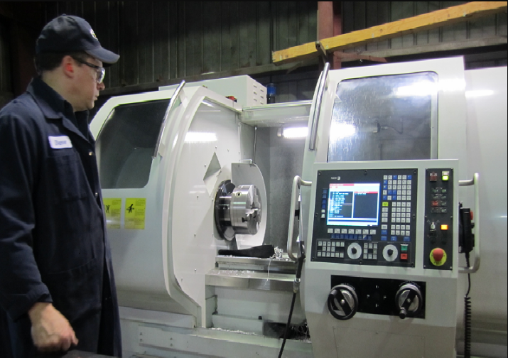
2. The Rise of CNC Lathes: Unleashing Precision and Complexity
With technological advancements, CNC (Computer Numerical Control) lathes emerged, opening up a new realm of possibilities. These modern marvels can boast up to 6 axes, offering a myriad of machining capabilities that were once beyond imagination.
3. Understanding the 6-Axis CNC Lathe: Precision Redefined
In the realm of CNC lathes, the 6-axis system is the pinnacle of engineering finesse. Here’s a breakdown of the six axes and their functions:
- X, Y, and Z Axes: These are the linear axes, responsible for the lateral and axial movements, allowing for complex cutting patterns and contouring;
- A, B, and C Axes: These represent the rotational axes, introducing the ability to tilt and swivel the workpiece, resulting in multi-angle machining.
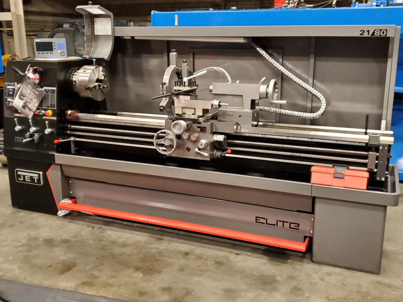
4. Anatomy of a Lathe: The Core Components
To comprehend the workings of a lathe, it’s essential to understand its core components:
- Chuck and Spindle Assembly: This vital component holds and rotates the workpiece at high speeds, enabling efficient machining;
- Tool Post: The tool is securely fixed on the tool post, which moves along the X and Z axes, determining the precise depth and position of the cut.
5. Machining Operations: Unleashing Creativity
Lathes are veritable masterpieces, capable of performing an array of operations that shape raw materials into refined products. Here are some common operations:
- Facing: Creating a smooth surface at the end of the workpiece;
- Turning: Reducing the diameter of the workpiece to achieve the desired shape;
- Tapering: Gradually changing the diameter of the workpiece along its length;
- Knurling: Producing a textured pattern on the surface for enhanced grip and aesthetics;
- Threading: Creating precise, threaded surfaces on cylindrical objects;
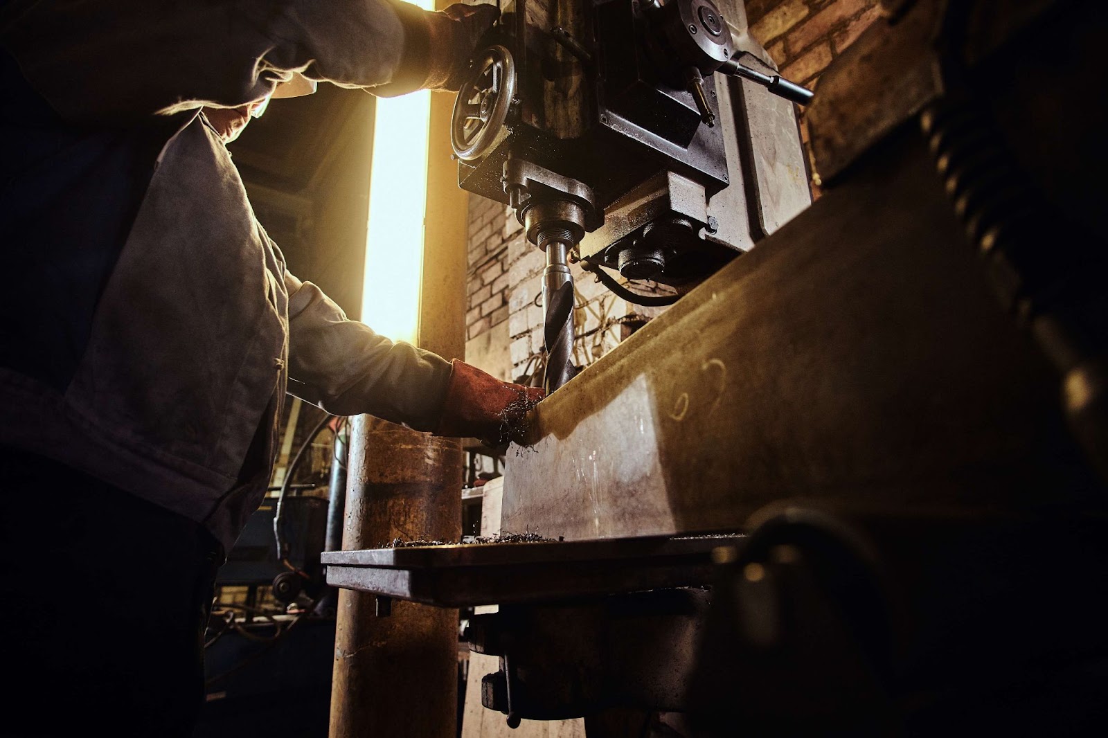
- Boring: Enlarging existing holes with utmost precision;
- Drilling: Making holes in the workpiece.
6. Advantages of Higher Axis Systems
While a 2-axis lathe can handle various tasks, higher axis systems offer several advantages that make them indispensable in advanced manufacturing:
- Greater Accuracy: Multi-axis lathes allow for intricate cuts and contours, resulting in highly accurate and finely finished products;
- Enhanced Efficiency: The ability to perform multiple operations in one setup reduces production time and increases productivity;
- Complex Geometries: With more axes at their disposal, engineers and designers can craft intricate geometries with ease, unlocking new design possibilities;
- Reduced Setup Changes: Multi-axis lathes streamline the manufacturing process by reducing the need for frequent setup changes, saving time and minimizing errors.
Unleashing the Potential of CNC Lathes: A Comprehensive Guide to the Different Axes and their Applications
Computer Numerical Control (CNC) lathes have heralded a new era in the realm of machining, transforming conventional lathe machines by achieving unprecedented levels of accuracy and efficiency. Their superior performance can be attributed to the complex interplay of numerous axes operating in synchrony, all under the supervision of an advanced computing system. In this detailed manual, we will journey into the intricate landscape of CNC lathe axes, investigating their functions and uses. This will equip you with the understanding required to fully exploit the capabilities of these extraordinary machines.

Linear Axes: The Compass of Tool Movement in XYZ Dimensions
The lifeline of any CNC lathe can be traced to its linear axes – the quintessential X, Y, and Z axes. These axes orchestrate the cutting tool’s trajectory along the vertical, horizontal, and depth dimensions of the object being worked on. Bestowing the CNC machine with three degrees of freedom, the linear axes enable the tool to navigate with remarkable precision within the XYZ spatial framework.
Implementations of Linear Axes:
Elementary CNC lathes employ a binary-axis system (incorporating the X and Z-axis), mirroring their more conventional counterparts. These machines excel at automating routine lathe operations while enhancing precision and consistency.
Rotational Axes: Transforming Potential into Tangible Outcomes
The rotational axes add an intriguing aspect to the workings of CNC lathes by facilitating the rotation of either the workpiece or the cutting tool along the X, Y, or Z-axis. Each of these rotational axes is symbolized by a distinct letter: A, B, and C.
- A-axis (Roll): This axis correlates with the X-axis and supports the rotation of the tool around the X-axis. It introduces the “roll” motion, facilitating intricate carving and sculpturing of the workpiece;
- B-axis (Pitch): Having a correlation with the Y-axis, the B-axis authorizes rotation along the Y-axis, introducing the “pitch” motion. This attribute proves vital when handling cylindrical or conical shapes;
- C-axis (Yaw): Centered around the Z-axis, the C-axis encourages rotation along the Z-axis, initiating the “yaw” motion. This functionality proves highly beneficial in creating helical or spiral designs.
Utilizations of Rotational Axes:
CNC lathes outfitted with rotational axes have the capability to generate intricate geometrical patterns with exceptional accuracy and productivity. These machines find significant applications in sectors such as aerospace, automotive, and healthcare, where the demand for sophisticated and curved components is high.
Incremental Axes: Augmenting Versatility in CNC Programming
The incremental axes system, encompassing the U, V, and W axes, endows CNC programming with remarkable adaptability. Although these axes don’t expand the degrees of freedom for the machine, they hold a pivotal role in positioning the tool with extreme precision along the X, Y, and Z-axis.
Implementations of Incremental Axes:
The U, V, and W axes enable incremental displacements, making tool alignment and machining more effective. These supplementary axes prove essential while crafting complex shapes and outlines, substantially reducing the operation cycle time without compromising on precision.
Unlocking the Secrets of CNC Lathe Programming: UVW vs. XYZ Axis System
In the world of CNC lathe programming, where creativity and precision converge, lies a crucial aspect that governs the positioning of the cutting tool – the enigmatic G-codes. These mystic codes hold the power to orchestrate the intricate dance of the tool within the XYZ plane, executing the most intricate machining maneuvers with flawless accuracy.
The Power of G-Codes:
G-codes serve as the backbone of CNC lathe programming, dictating the tool’s movements, speeds, and actions. These codes are the language of the machine, enabling it to interpret instructions from the programmer and translate them into tangible results. By harnessing the power of G-codes, programmers can unlock the full potential of CNC lathes, producing awe-inspiring creations limited only by their imagination.
Unveiling the XYZ Plane:
The XYZ plane serves as the canvas upon which the CNC lathe brings dreams to life. In this three-dimensional realm, the X-axis represents the horizontal movement, the Y-axis controls the vertical motion, and the Z-axis commands the depth of the cut. By skillfully orchestrating these axes, programmers can sculpt intricate shapes, cut precise threads, and create beautifully contoured surfaces.
Navigating the Coordinate Systems:
The key to unraveling the mysteries of UVW and XYZ axis systems lies in understanding the two types of coordinate systems used in CNC lathe programming:
A. Absolute Coordinate System:
- The absolute coordinate framework utilized by programmers prescribes precise X, Y, and Z coordinates in the space where they aspire for the tool to manoeuvre;
- These coordinates gain their definition from the reference point of the machine, frequently referred to as the origin, which serves as the initial position for all operations;
- Programmers adopt absolute numerical values, thus designating exact locations within the workpiece for the tool’s traversal.
B. Relative Coordinate System:
- Contrasting the absolute system, the relative or incremental coordinate system illustrates the tool’s motion in relation to its existing position;
- This implies that programmers stipulate the measure of distance and the intended direction of the tool’s journey from its current location, rather than referring to an unvarying point;
- The relative coordinate system proves advantageous during the execution of recurring tasks, as it facilitates the tool’s movement incrementally from one point to another with remarkable ease.
Exploring Positional and Incremental Coordinates in CNC Machining
There exist two primary strategies for positioning the cutting implement, namely absolute coordinates and relative coordinates. Each technique presents its own merits, and a comprehensive understanding of their operation can notably influence the effectiveness of CNC procedures.
Absolute Coordinates:
The technique of absolute coordinates revolves around locating the cutting implement concerning a stationary reference point, often referred to as the datum point or origin. This point plays the role of the initial position for all tool movements throughout the machining process. The following sequence elucidates the application of absolute coordinates:
System Engagement and Dimensional Unit Configuration:
The G90 command instigates the activation of the absolute coordinate system.
G21 designates the unit of measurement as millimeters, guaranteeing uniformity and accuracy during the machining phase.
Cutting Pace and Direction of Spin:
S450 determines the speed of cutting, influencing the rate at which the tool feeds.
M04 dictates the direction in which the tool rotates.
Implement Maneuvering:
The instruction “G00 X20.0 Y20.0” triggers a swift motion towards position ‘A’, with both X and Y coordinates fixed at 20.
Staged Relocation:
Maintaining constant Y-axis coordinates, the tool relocates to position ‘B’, where the X-coordinate in relation to the datum point is 40.
In a similar fashion, the tool advances to position ‘C’, with the X-coordinate relative to the datum point recorded as 60.
Process Termination:
The operation culminates by ceasing the spindle and retracting it to the original point ‘O’, assuring proper handling of the tool and minimizing potential errors.
Guidelines for Utilizing Spatial Coordinates
Make sure to validate the reference point to avert inaccuracies in positioning. Uphold a uniform and precise metric system to attain exactitude. It’s crucial to perform habitual calibration of the CNC machine to preserve its precision over time.
Relational Coordinates:
Contrarily, relational coordinates concern positioning the cutting instrument in relation to its immediate location. Rather than using a stationary reference point, the tool shifts gradually from its existing position. Here’s a walkthrough of how relational coordinates are implemented:
Initiating Relational Mode and Setting Units:
The G91 command instigates the relational mode, permitting the tool to shift progressively from its existing position. G21 standardizes the measurement units to millimeters, facilitating consistency and user-friendliness.
Determination of Cutting Velocity and Orientation:
S600 defines the cutting velocity, setting the tool’s feed rate for optimal performance. M03 designates the rotation direction, safeguarding appropriate cutting.
Orchestration of Tool Movement:
The G-code “G00 X20.0 Y20.0” positions the tool at coordinates X=20 and Y=20, or position ‘A’.
Relational Displacement:
Divergent from spatial coordinates, the tool relocates to position ‘B’ by progressively augmenting the X-coordinate by 20 units. In the same manner, the tool proceeds to position ‘C’ by adding another 20 units in relation to its immediate position at ‘B’.
Interpreting Modality:
Programming in both absolute and incremental modes exhibits modality, implying they stay operative until explicitly supplanted by the alternative mode. To revert to positional coordinates, the G90 command serves the purpose.
Suggestions for Effective Use of Incremental Coordinates:
Devise tool movements cautiously to evade collisions during progressive displacements. Monitor the tool’s existing position to guarantee precise incremental relocations. Validate the incremental values to eliminate the chances of exceeding or falling short of the intended positions.
Conclusion
To conclude, acquiring a comprehensive understanding of the vital rotational theories related to lathe axes is a crucial turning point for anyone yearning to become a skilled machinist or for those already established in the field. We have immersed ourselves in this piece, deeply exploring the fundamental doctrines that regulate the movement and positioning of lathe implements, offering us insight into the complex interaction among different axes.
Recognizing the importance of tool offsets and comprehending the influence of workpiece coordinates are indispensable elements as we strive to perfect our grasp of lathe axes. These aspects lay the groundwork for successful tool manipulation and accurate carving, providing us with the means to enhance machining procedures and reduce inaccuracies.